|
www.ropeantenna.com |
 |
|
 |
|---|---|---|---|
|
|
|||
|
|
|
|
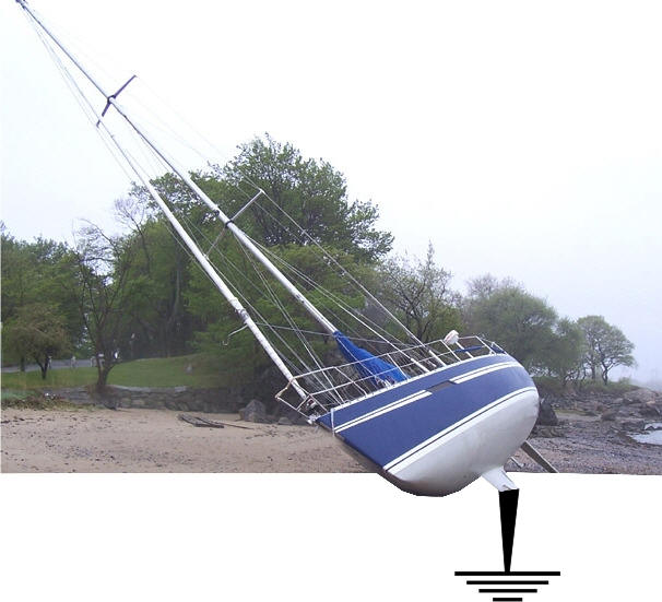
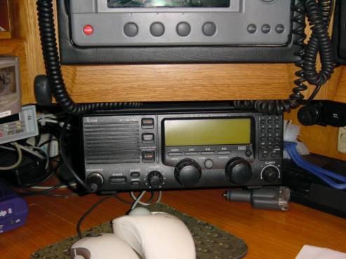
Well, you would have chosen a high quality transmitter / receiver unit such as the ICOM IC-M710 with an ICOM AT-130 automatic tuner unit. You will have chosen an aerial option (whip, backstay or halyard), a separate dedicated radio battery and charger, and a way of getting the whole system earthed into the ocean such as a grounding plate like the “WonderBar”,DL Lilly, or “Dynaplate. Or, better now the new Ground Shoe, which is much smaller in size, 2 1/2 times the surface capacity and only 2 through rods ,with only 3/8 holes. This New grounding shoe is truly a new design and works even better then old previous models.
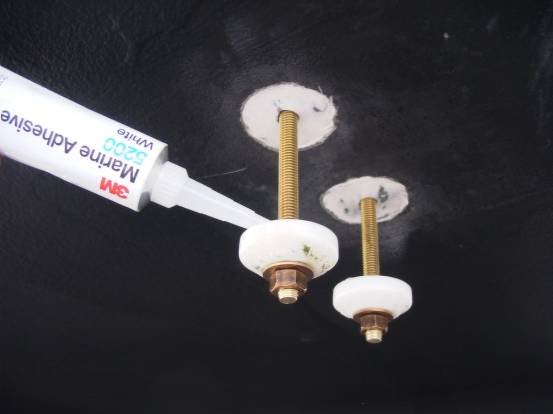
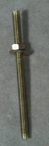
Let’s start under the water. For a good earth (assuming you are not steel hulled) you will have to haul the boat to install a grounding plate. It should be installed as deep as possible and as close to the centerline as possible to ensure it’s always covered with water, and when you install it, it should “hang off” of the boat so that the plate has water on all of its faces to maximize its earthling area. Do not bond it to the hull using 5200 between the plate and the hull or you will regret it! If you short cut the grounding process by earthing to the engine block or a keel bolt, you may as well throw the whole lot overboard as the “noise” and interference you will get, will make the radio annoying and maybe unusable. On our boat (a 61ft Oyster sailing yacht called “Talisman”), we chose the Mark VII Wonderbar (21” long x 7” wide x ½” thick) as a grounding plate. The new Ground Shoe by RopeAntenna was not available at this time. This comes with 5 holes, 5 countersunk screws and 5 seals called “WonderSeals” which keep the water out of the boat if installed properly! But now, you need to review and consider the smaller but more efficient Ground Shoe, with only two holes. We basically threw the screws that it came with away, [money wasted]and invested in a 6ft long length of Bronze Silicon threaded stud (the same diameter as the holes in the plate) and cut it into 5 equal 14” lengths using a band saw, cleaning the threads afterwards. Bronze Silicon stud is the best metal for conduction of “earth” and although it’s expensive, it’s not much in the grand scheme of things.
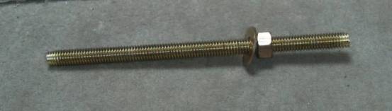
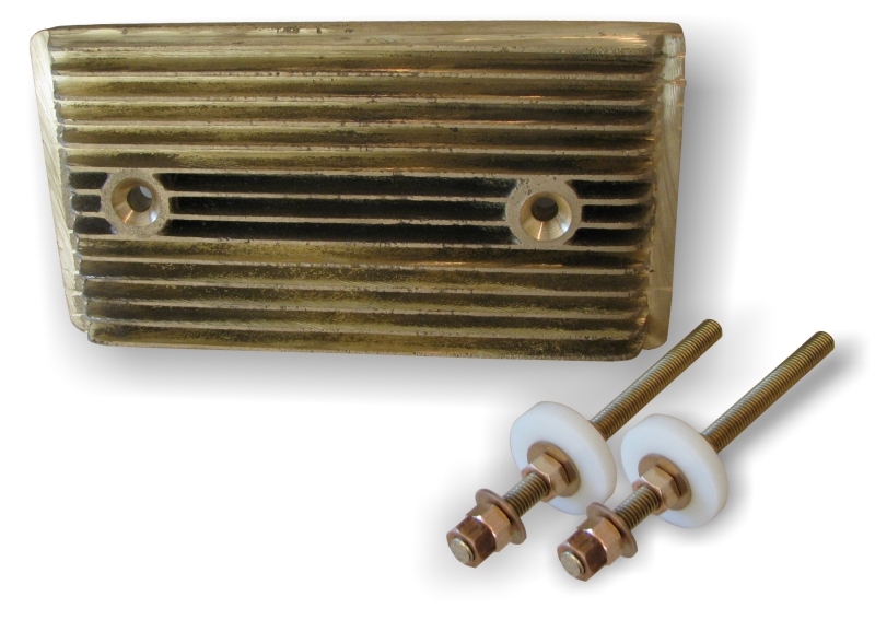
The Bronze Silicon Stud, nut and washer. Expensive but worth it! We also bought an additional 5 “WonderSeals” to complete the install of the plate so that we have a seal on the inside and the outside of the hull. A bit over the top maybe but it’s a good, easy and cheap way to make sure it doesn’t leak. We have just sailed over 5000Nm in 4 months with this install and it hasn’t leaked a drop and the quality of our signal both sending and receiving is fantastic. The longer studs and suspended grounding plate basically enables us to dive on the boat at any stage and remove the plate to clean it. That way we don’t have to haul and we keep our radio performance in peak condition. The plate does tend to clean itself when you transmit on the radio but if you don’t use it for any length of time, it soon clogs up. It is quite common for people to dive on their yachts in the tropics to attempt to keep their hull clean, unless they have a very good antifouling (such as Micron 44 or 66) suitable for that type of water and usage. The antifouling you choose to paint your yacht with is another important point to bear in mind before you attempt to sail to warmer climbs. Unless (of course) you want to haul and re-paint when you get there. Mind you, scrubbing your hull by hand underwater is a good way to combine a swim with a keep fit class!
Next, we have to carefully and accurately drill the holes in the hull to fix and connect the plate to the “inside world” of your yacht. On the waterside of the hull around the holes, it is important to remove any antifouling equal or greater in area to the footprints of the “WonderSeals” so that they can adhere to the hull in a strong and watertight way. You can antifouling the area again after the install but the seals must have a good solid surface to stick to. A Dremmel tool is good for this. The area should obviously be sanded flat before fixing to.
Carefully drill Holes to suit the grounding plate. Remove the bilge paint and antifouling from both inside and outside to ensure a good bond to sound surfaces. It’s normally easiest to drill from the outside. Have a vacuum cleaner sucking from inside the boat to catch the mess and stop debris clogging up your limber holes in your bilge.
Notice that the antifouling has been stripped back ready to receive the seals and adhesive. The seals have a donut recess in them to take the sealant. Placed like this, it allows you to add the sealant with minimal mess, then just push them up against the hull and tighten the nuts on both sides. Don’t forget to run some 5200 up the holes in the hull and around the threads of the studs.
Add the marine sealant (Use 3M 5200 – permanent bond for best results) to the seals both inside and outside and tighten the nuts up on both sides allowing 24hrs to “go off” before fitting the plate and copper foil strip inside the boat.
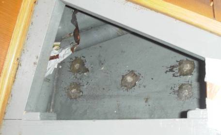
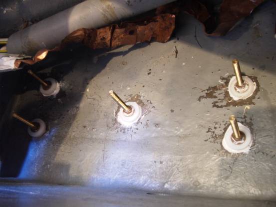
The 5 studs and seals are now in place ready to take the plate outside and copper earthing foil inside after the sealant has had time to go off. Mineral Spirits can be used effectively to remove excess sealant and to clean the threads, and your tools. Don’t go too mad though. It doesn’t matter that you can see some sealant around your seals and studs. Just a light wipe is all I would suggest. I always worry that it will affect the “setting” of the sealant if you use too much.
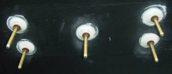
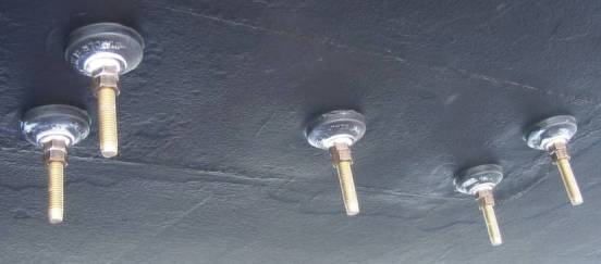
Outside, the finished seals are ready to take a couple of coats of antifouling. Do not paint the studs.
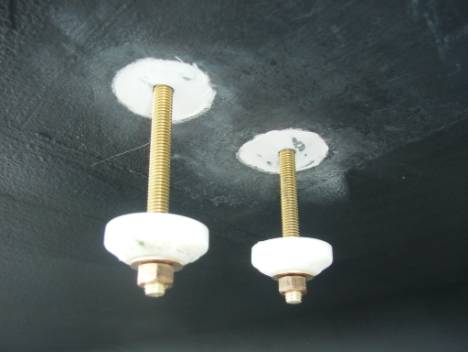
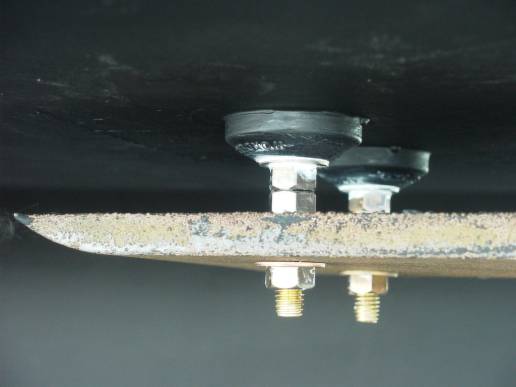
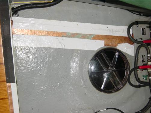
And the finished thing, ready to take the Grounding shoe. Note the double nuts to lock the studs in place.
The finished product. The manufacturer’s countersunk screws are replaced with 14” long Bronze Silicon studs (length depends on the thickness of your hull) so that the plate can be removed with ease for cleaning. Also the plate is suspended from the hull to maximize the surface area for grounding purposes.
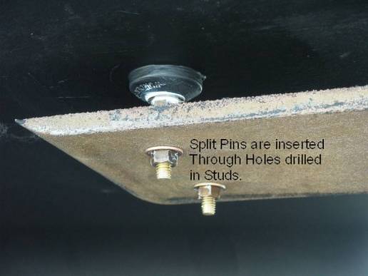
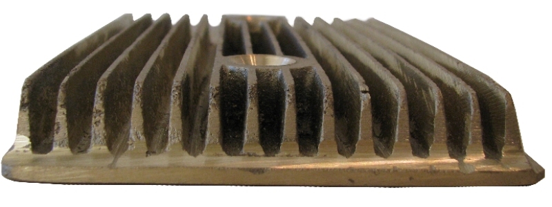
This plate is not new and has been re-used over the past 2 years and still going strong. Muriatic acid (The old name for hydrochloric acid (HCl)) is great for cleaning it up like new but wear goggles and gloves, as it’s very corrosive. The plate does tend to clean itself when you transmit on the radio. The ends of each stud were drilled through and split pins inserted to stop the final bolts from dropping off. UpDate: A newer Grounding plate available from RopeAntenna has only 2 studs (easier to install) and has fins that increase the surface area and hence better grounding, and comes with the silicon bronze studs, nuts, washers and instructions.
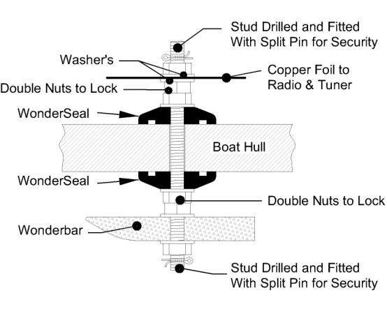
Sectional Diagram Illustrating the Installation of the Grounding Plate, seals and studs
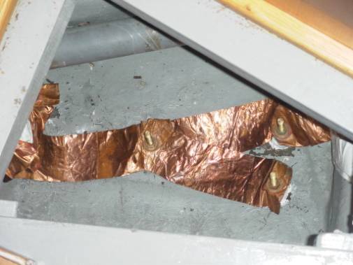
Copper foil is run to every stud to maximize the use and area of the grounding plate. This plate is purely for the SSB radio. There is a second smaller grounding plate for the electronics, which massively reduces radio interference and noise. Why foil? Round wires create inductive reactance at radio frequencies, and are not effective as a good grounding conveyance. Use 1 or 2 inch wide, 5 mil copper foil (available at most marine stores or plumbing supply houses) to achieve a good seawater ground. Technically should you measure the "RF" resistance it should be between 4 to 12 ohms to salt water.
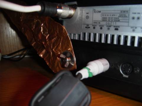
One end of the copper foil is connected directly to the back of the radio unit itself. Fold the foil 2-3 times being careful not to cut yourself (it’s very sharp) and drill it through so you have a good connection. Do not be tempted to earth anything else to this foil. It is VERY important that you do not attempt to connect the radio or tuner or any part of your radio system to earth using a wire no matter how thick it is. Copper foil is all you should use throughout; as wire develops a resistance to earth and will severely affect your whole system.
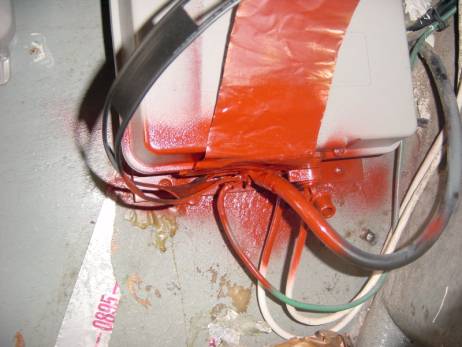
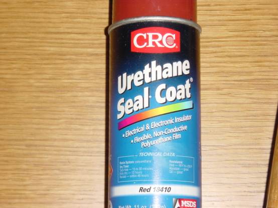
The other end of the copper foil is connected directly to the automatic tuner (mounted in the lazarette in this case) and all of the electrical connections are covered with a Urethane Seal Coat aerosol paint to reduce corrosion as much as possible.
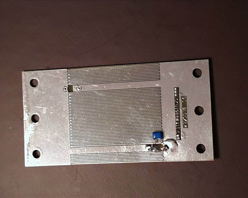
Polyurethane Non Conductive Seal Coat to protect connections from the elements. In between the radio and the grounding plate we installed a DC Block, which is simply a couple of one-way diodes to stop any DC voltage looping around in the system. This dramatically reduces noise in your radio system.
This DC Block is specifically designed for marine frequencies and is available from RopeAntenna.
The foil can be folded neatly to run through the boat but you should avoid scrunching the foil. Staples are useful to hold it in place. Run duck tape over the edges of the foil so that it doesn’t get damaged and also you won’t cut yourself next time you have to work around the foil. Cover the rest of the copper with a thin coat of paint or epoxy to keep it clean and un-tarnished. Do not cut the foil unless you absolutely have to. There is always somewhere else to run the foil. Don’t rush this part. Take your time and you will reap the benefits.
The best and only wire to use is GTO-15 cable. This wire may not look like much but it is insulated and can carry 15000 volts. Always clean, solder and heat shrink any connections.
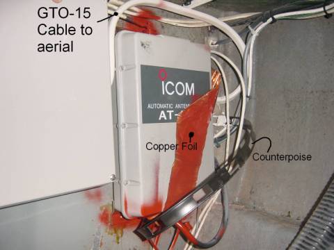
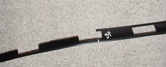
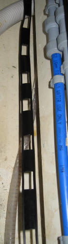
You will see the connection of the GTO-15 cable on the top of the tuner. Note the heat shrink and the application of the Polyurethane Sealer paint. The other important thing to notice is the Counterpoise wire. This is the black flat plastic strip of wire with holes cut out of it. This runs from the tuner in the lazarette all the way to the bow locker (about 75ft in total) and the radio waves use this as a “Springboard” when you transmit giving you extra range and a much clearer signal. The whole installation is finished by strapping all the cables and wires down using cable ties and wire hold-downs (not shown here).
The GTO-15 cable comes through the deck via a waterproof deck flange fitting and runs up to the aerial of your choice. There are 3 types of aerials you can have installed on your yacht.
What we use on Talisman is both the halyard aerial which is a new addition, plus the old measured backstay aerial as a backup. The GTO-15 cable comes from the tuner, through the deck flange and up the starboard backstay to a connector where we can choose which aerial to use. Recently Dr. John, the RF designer of the Rope Antenna has develope even better way to feed the Rope Antenna or any other type of antenna. GTO-15 is originally design to power neon lights as in dinners, and decorations on windows. GTP-15 has and not ever designed for RF feed line applications. There is no shielding or any other properties that make GTO-15 a good choice to be used for RF applications. The Rope Antenna and CruiseEmail engineering team now uses ¼ inch silver/nickel tinned brad. The brad is then inserted into high voltage plastic loom that is used in automotive applications. RF energy is a surface voltage and the brad give very low RF resistance form the antenna tuner to the actual antenna. When viewing GTO-15 the size of the internal wire is less then the size of a straight pin. This RF antenna feed line can also be purchased from RopeAntenna.com.
You will see that we are currently using the halyard aerial. The connections are tin soldered and heat shrunk after being covered with dialectic paste to prevent corrosion. There is enough slack in the wires to trim off and re-connect if necessary. We now replace the GTO-15 with the new brad loom feed line from RopeAntenna.com
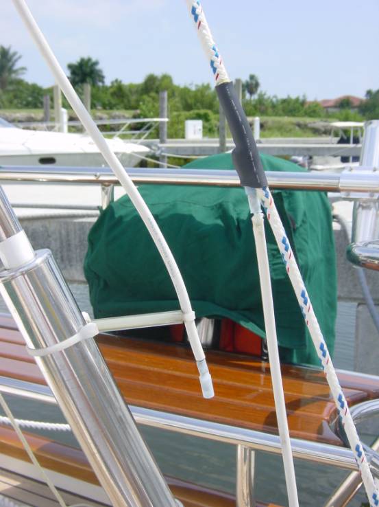
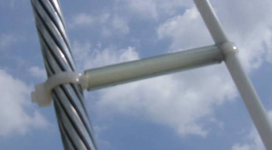
A good tip to avoid earthling your hard earned signal out to the un-insulated backstay is to hold the wire off of the backstay using plastic tubing and cable ties spaced every 2ft or so.
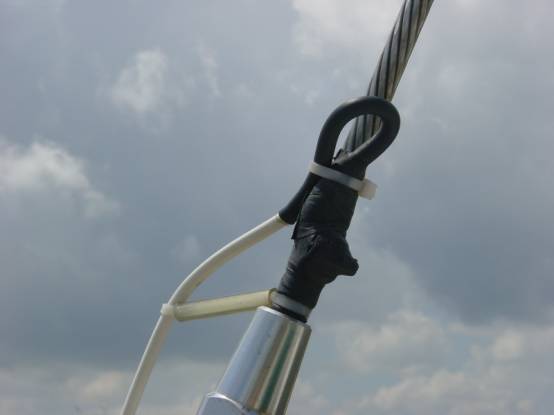
If you decide to use the backstay aerial option, run the GTO-15 cable up the backstay to immediately above the lower isolator (using the spacers every 2ft), again soldering, coating in dialectic solution and heat shrinking the connections. The wire can then simply be clamped to the backstay itself using a hose clamp or jubilee clip. If you introduce a loop in the wire as shown above, then any dampness will not be encouraged down to the connection itself but away reducing corrosion even more. To finish off, wrap the whole kit and caboodle in self-amalgamating tape. Remember that corrosion will quickly reduce the quality of any system installed on a yacht so you should always endeavor to make any connections as good as possible even if it does take extra time. You’ll be glad you did when you come to service or replace parts.
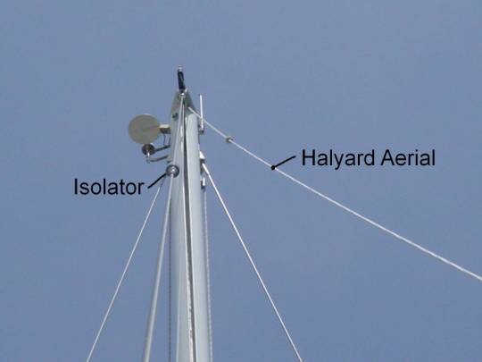
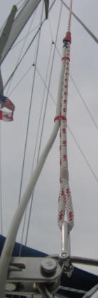
This photo taken from the stern looking up to the masthead, shows the halyard aerial (on the right) attached to a topping lift. It can be quickly and simply dropped and coiled when you don’t need it. I always drop and coil it away if there is a risk of a lightening strike and disconnect the backstay aerial. You will notice the isolator at the top of the backstay in a position to maximize the range of the radio.
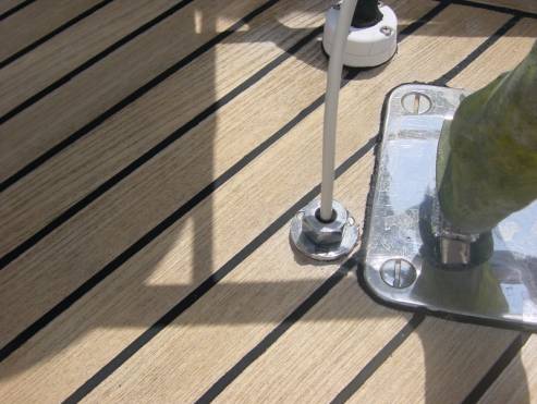
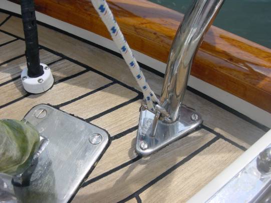
The bottom of the halyard aerial is simply shackled to the pushpit through the eye splice.
We haven’t talked about the installation of additional counterpoise wires in your installation as yet, so here goes. Your system will work without them but if you can be bothered to put in the work, you will certainly reap the benefits. What is a counterpoise? Basically a counterpoise is a springboard for your radio transmission to “bounce off” of into the atmosphere. Good grounding or counterpoise techniques are absolutely necessary for maximum single sideband range. Half of your antenna is your radio frequency (RF) ground. The radiating portion of your antenna needs to see a mirror image of itself before it will send out your SSB signal. This mirror image (called a counterpoise) is created by using a metal surface and seawater as your radio frequency ground plane. Your marine single sideband system will not perform satisfactorily if you don't have a good counterpoise system. Poor counterpoise (ground) equals poor range. This is especially true on lower frequencies where large RF grounds (counterpoise) are required for good range. Of course, for those of you with aluminum hull vessels, your RF ground plane (counterpoise) is your hull, and you'll probably have the loudest signal anywhere in the world. No further RF grounding is necessary for you lucky people. As an extra counterpoise (RF ground) to our ground plate and copper foil, we decided to install additional wires, which connect to the same point as the copper foil on your tuner. This then runs the entire length of the yacht right up to the bow if possible. A capacitive ground system such as this, made up of copper foil run around the hull below the water line, and individual copper strip wires at one-quarter wavelength sections, is one way to achieve a very good ground. The wire we used was basically 2 wires separated by plastic (available at most electrical shops). This allowed us to run two runs of cable at the same time. We then removed a 1.5ft length from one side of one of the wires at 37ft down the run from the tuner. These lengths correspond with the ¼ wave radial lengths required to match the most commonly used frequencies in the marine industry.
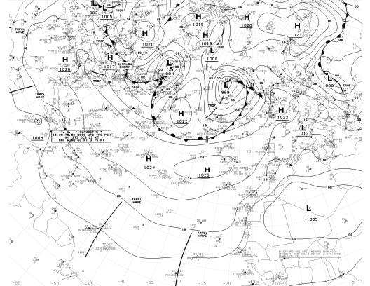
After all of this work, which took about a week to install completely, we popped Talisman back in the water and started to see how she worked. Here is image downloaded using “ICS Weather Fax” software on a laptop computer connected to the audio out socket of the SSB radio.
As you will see, the quality is excellent. And you can leave the software on permanently to grab the broadcasts when they are made or set up a schedule to download at the right times of day.
This is the finished installed radio set hung from the shelf above. It’s easy to use front end with large LCD display and positive feel knobs makes using it a pleasure.
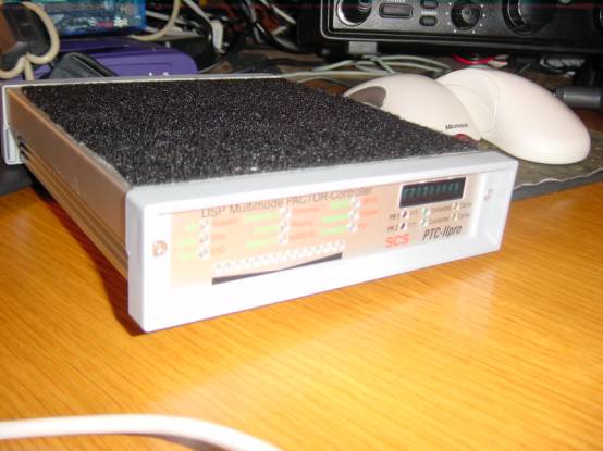
The Pactor PTC-II Pro is an excellent addition to the radio set for email and Internet access.
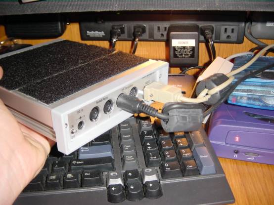
The connections are simple and it’s powered by the SSB radio itself. Note the graphite insulators that the wires are run through. These reduce noise and interference even more. I hope that this helps you install or re-install your SSB system so that you start to see the same results that I did. I am a fully qualified MCA Class 4 Master of yachts and have been running yachts professionally for 6 years, having started playing in boats at the age of 6. I have a lot to offer and if I can help you further, maybe with sourcing and sizing a halyard or backstay aerial, or your counterpoise, just drop me a line. You will find me through my web site at www.crew4sail.com Follow the “Contact Us” link. Here are some additional areas you can look at if needed, to reinforce your knowledge and resources: www.RopeAntenna.com link for Grounding Shoe grounding plates http://icomamerica.com/ ICOM’s web site. www.cruiseEmail.com email services www.ropeantenna.com SSB halyard antenna
|
The Bronze Silicon Stud,
nut and washer. Expensive
Ladder line for the
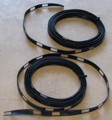
2 Coils of ladder line,
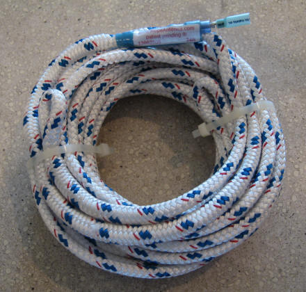
Rope Antenna coiled
|
|
| ||||||||||||||||||||||||
| |||||||||||||||||||||||||||